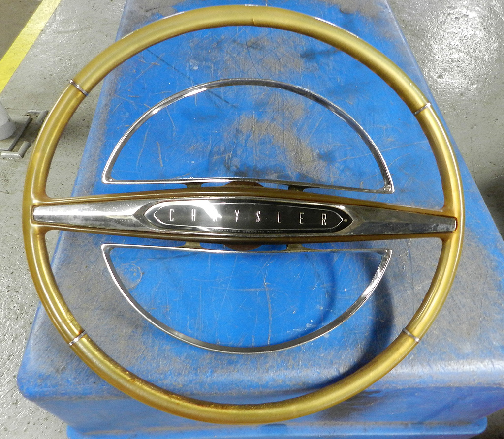
1964 Chrysler 300K Ram Coupe
Tilt Wheel Turn Signal System
|
1964 was the first year Chrysler offered a tilt steering wheel. Rather than develop their own,
Chrysler bought the assembly from the Saginaw Steering Gear division of GM.
No surprise, there
are some unique things here ...... the steering
wheel does not interchange with Chrysler wheels,
and the turn signal switch is a special nightmare all its own.
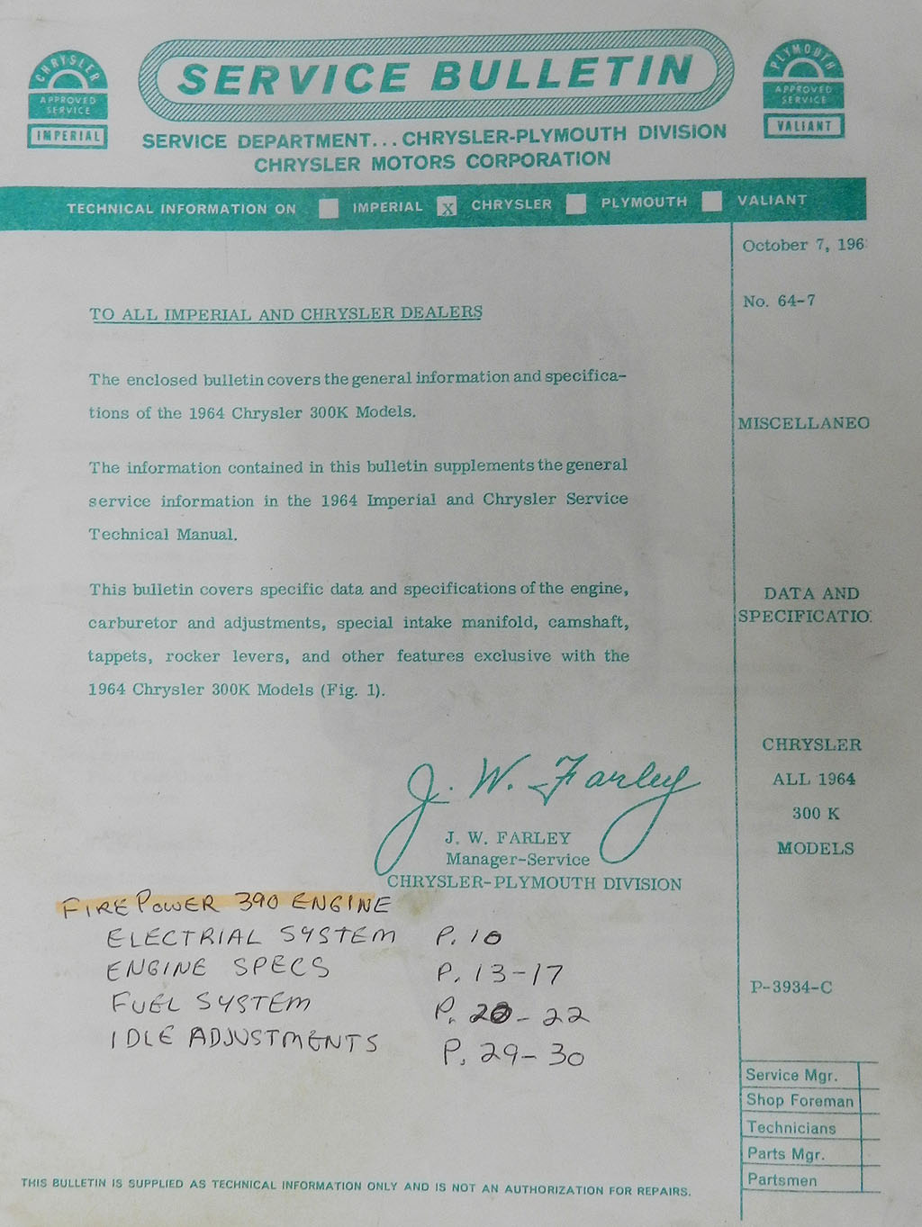
There is very little information on the turn signal system in either the Chrysler or GM service manuals. If you can find the Chrysler Service Bulletin number 64-7 dated October 7, 1963, pages 38 to 50 have some information on the tilt mechanism but nothing on the turn signal. The other Chrysler 300 club also has a Chevy training program booklet, see here. Without much to go on, I took out my spare tilt wheel column and started to learn how it works. The spare column is brown. The car needing the repair has a black column so you may notice the difference. |
|
|
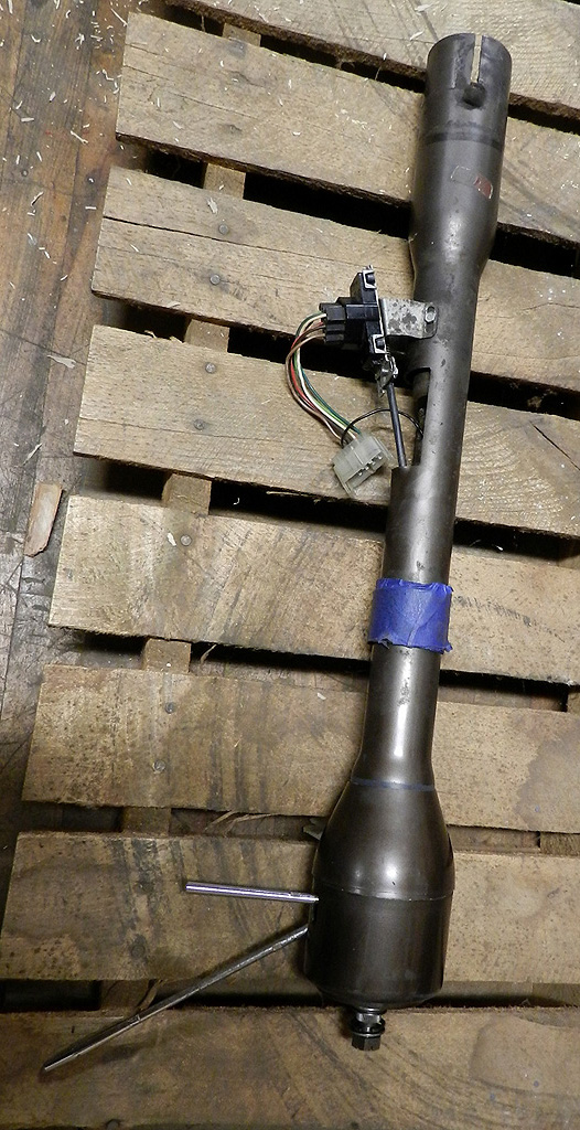
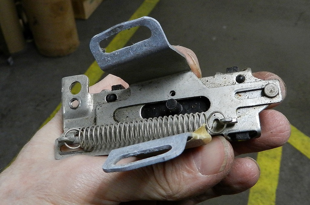
If you were to remove the steering column from the car and remove the
steering wheel, this is what you would have. The tilt lever releases the
locks inside the head allowing the steering wheel to move to 3 positions.
The manual says there are 7 positions -- I find only 3 although the tilt column used in the Imperial
has more positions (5).
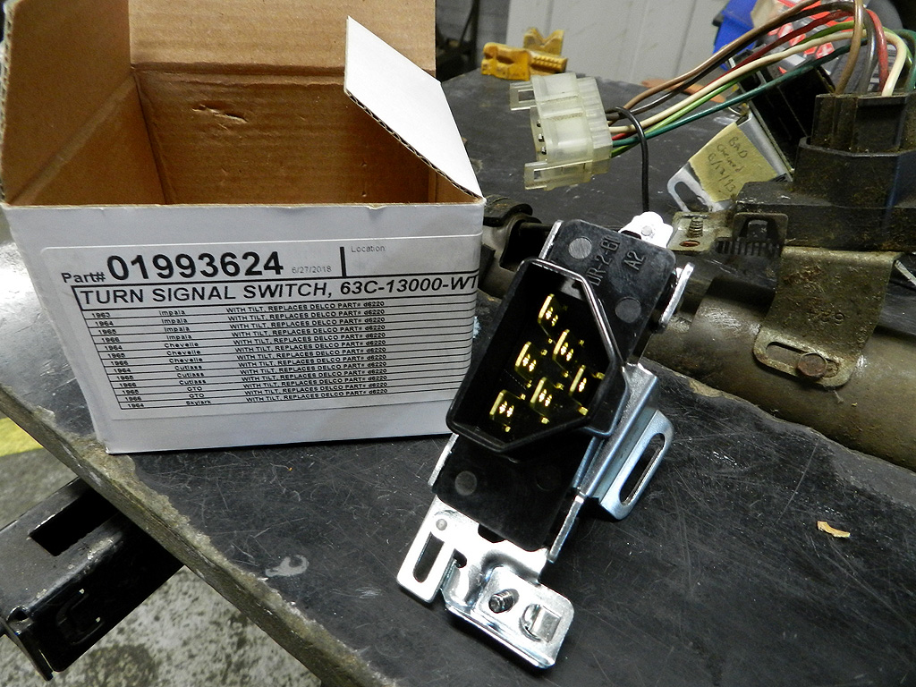
The turn signal lever actuates a mechanism inside the head which moves the piano wire inside a Bowden cable. The Bowden cable runs down the column to the turn signal switch, which is at foot level. For proper operation of the switch system, there are three critical items. The first is a good turn signal switch. Given its location and age, switches get sticky as well as lose electrical integrity. For less than $100 you can buy a new switch -- Ebay. The second is the piano wire inside the Bowden cable. I haven't had one break, but they can. If you can't replace the piano wire you will have to buy a new Bowden cable. They are available on Ebay (see 1964-66 GM tilt column) but they are longer than originals and require modification. The third key is the Bowden cable sheath. This is important because as the steering colum head tilts, this draws the piano wire upward. If the turn signal switch did not also move as the wire moves, this would cause the switch pin to move from the neutral (off) position to the upper (left turn) position. So they designed the switch to slide on a spring loaded base and have the switch move with the head tilt by the cable sheath. In this way, the relative position of the switch pin to the switch is maintained as the column head tilts. |
|
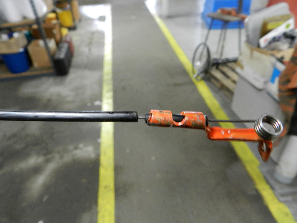
On the original cables, this sheath is plastic.
After 55 years, the plastic breaks -- sometimes it breaks at the head, sometimes at the
base, and sometimes at both locations. With a break, you lose proper function of the turn
signal system, especially at max up tilt.
If you click the picture you will get a close up view of the Bowden cable up in the column head. There you can see that the black sheath has broken and pulled away, exposing the piano wire. The new replacement cables have the sheath as wrapped cable -- it will last forever. But, the new cables are 19" long and the originals are 17.375" so you either have to modify the new one or repair the original. I decided to repair the original. On this column, the sheath was only broken in one location. I was able to repair the section with the heat shrink tubing. On the other column, the sheath had broken at the head and at the tail. I was able to repair both ends with heat shrink although the tail required some extra work. |
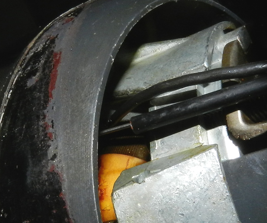
Cable removed, broken sheath visible 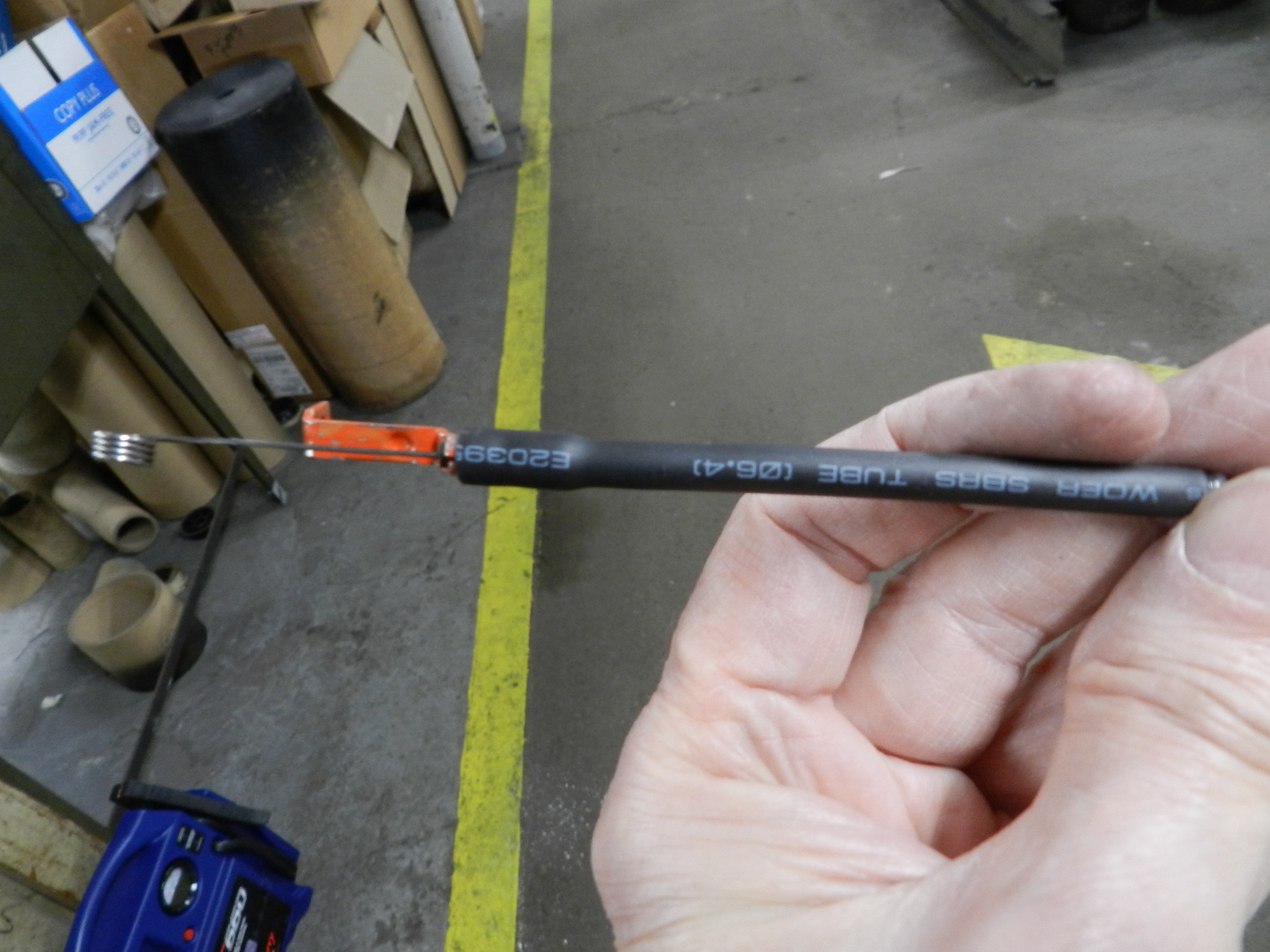
Cable repaired |
|
The underside of an old original switch, showing the
switch pin. The middle position of the switch is the OFF
function. From the center of this position, the pin can move .1625" each way
and still be in the OFF mode. The right and the left (ON) positions
each have .275" in their ON modes and so the total travel of the switch pin
is .875". The slots in the switch base allow you to
adjust so the OFF position is centered in the switch.
|
|
|
We have videos here for the
disassembly,
|
|
Back